
ABYC publishes updated battery and electrical standards
ABYC published updates to their E-11 and E-13 standards. E-11 covers the basic requirements for AC and DC systems on a boat. E-11 is a mature standard and the revisions reflect that maturity. This is the first revision of ABYC’s E-13 lithium ion battery standards. The first publication of E-13 incorporated most of ABYC’s technical note TE-13 that previously provided recommendations for the installation of lithium batteries on a boat. Hence, the updates to E-13 are more extensive.
I participated in ABYC’s standards week in San Antonio, Texas earlier this year as well as several other standards development meetings. I’ve previously posted about my experience in those meetings, but seeing the finished product reinforces the value of having attended.
E-11 updates
The updates to E-11 are quite numerous. But, for most Panbo readers who may be taking on LiFePO4 retrofit or other DIY projects, the biggest updates cover amp interrupting capacity (AIC) requirements for over current protection (OCP) devices for all batteries and the use of solid state OCP devices.
AIC requirements mature
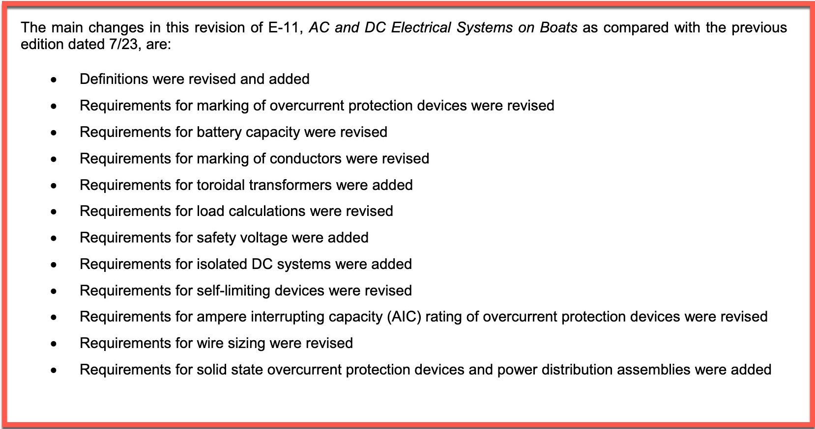
The previous version of E-11 provided a table for AIC requirements for lead acid batteries but not for other chemistries. Instead, the standard relied either on manufacturer provided short circuit rating — a rarely provided spec — or a 20,000 amps at 125 volts DC. Those requirements effectively pushed all but the smallest LiFePO4 installs towards requiring a Class T fuse.
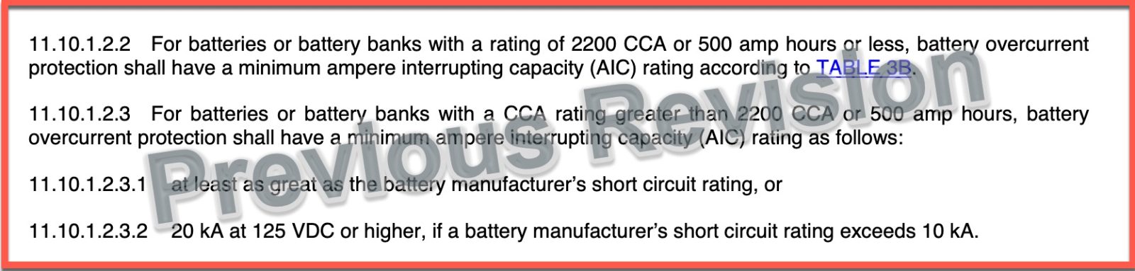
I had to read 11.10.1.13.1 and 11.10.1.3.2 several times to be clear that the first paragraph only applies for flooded lead acid batteries. If you’re installing anything other than flooded lead acid batteries, 11.10.1.3.2 governs.
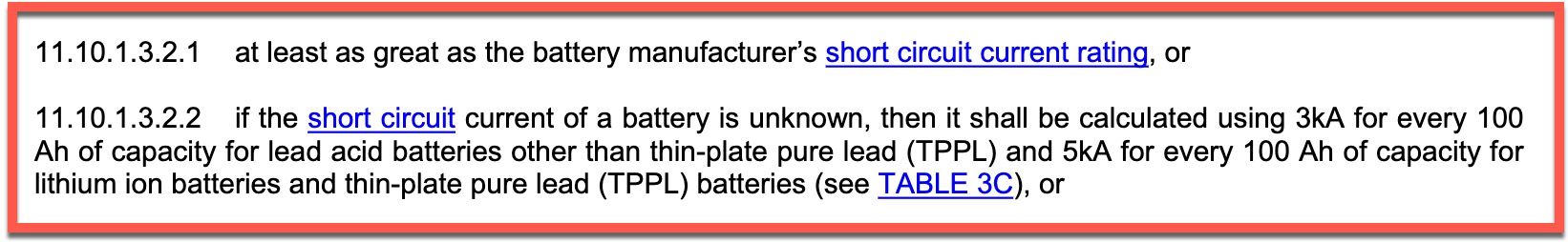
The standard’s first choice for determining AIC requirements is the battery manufacturer’s short circuit current (SCC) rating. However, the reality is that very few battery manufacturers publish this information. So, for those cases in which SCC isn’t available, E-11.10.1.3.2.2 now provides a simple formula for determining AIC requirements. For lead acid batteries — other than thin plate pure lead which produce higher short circuit current — the standard requires 3,000 amps of interrupt capacity per 100 amp hours of battery capacity. For TPPL lead acid and lithium ion batteries, the requirement is 5,000 AIC for each 100 amp hours of capacity.
Applying these new formulas, a 300 amp hour lead-acid battery bank would require an OCP with 9,000 AIC rating. That same 300 amp hour bank in lithium ion would require 15,000 AIC rated OCP.
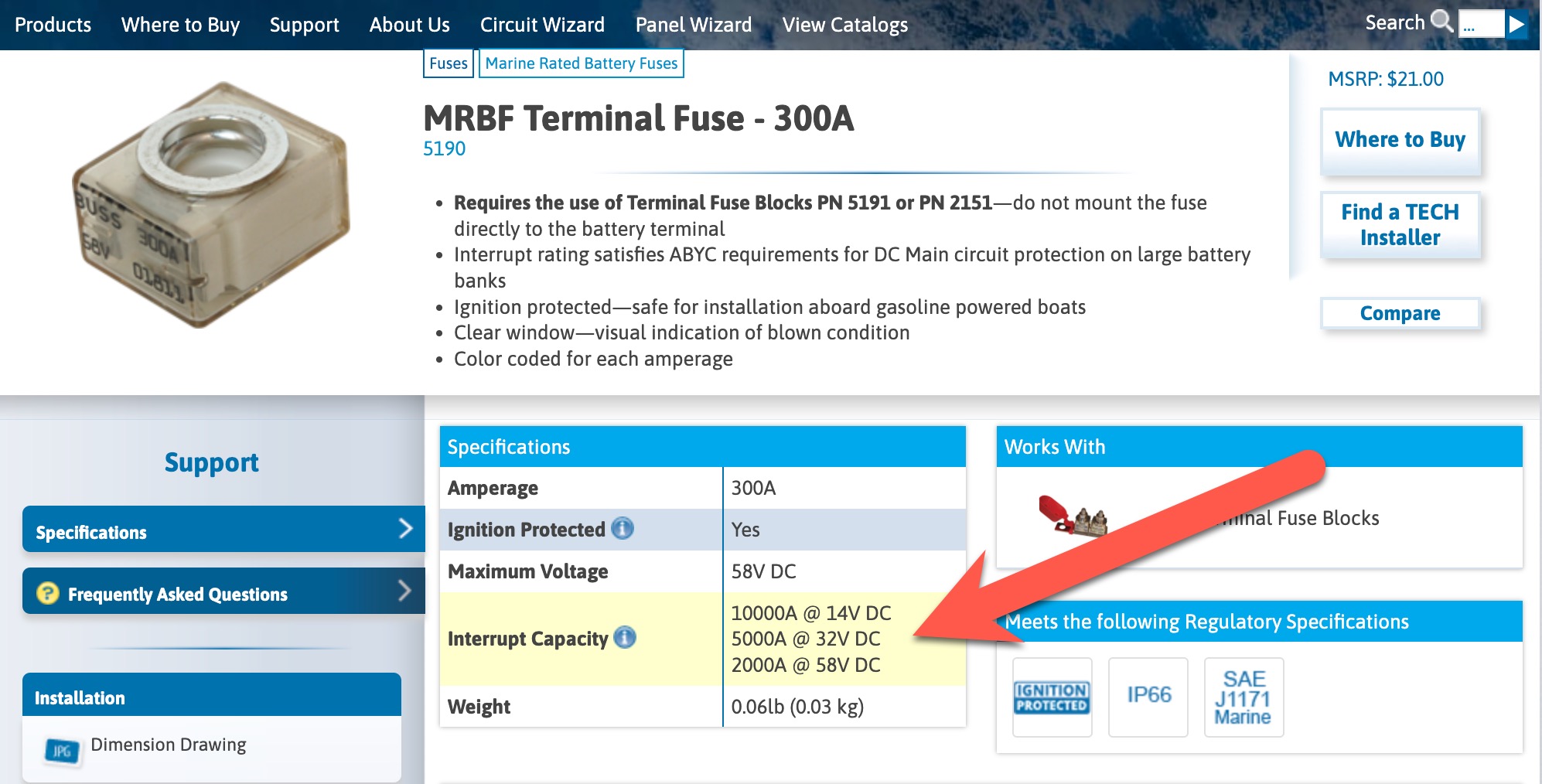
Smaller batteries and battery banks can utilize MRBF and other fuse types. MRBFs are particularly attractive as they can be installed directly on the positive post of the battery and avoid any unfused conductor.However, it is important to pay attention to both rating and voltage.
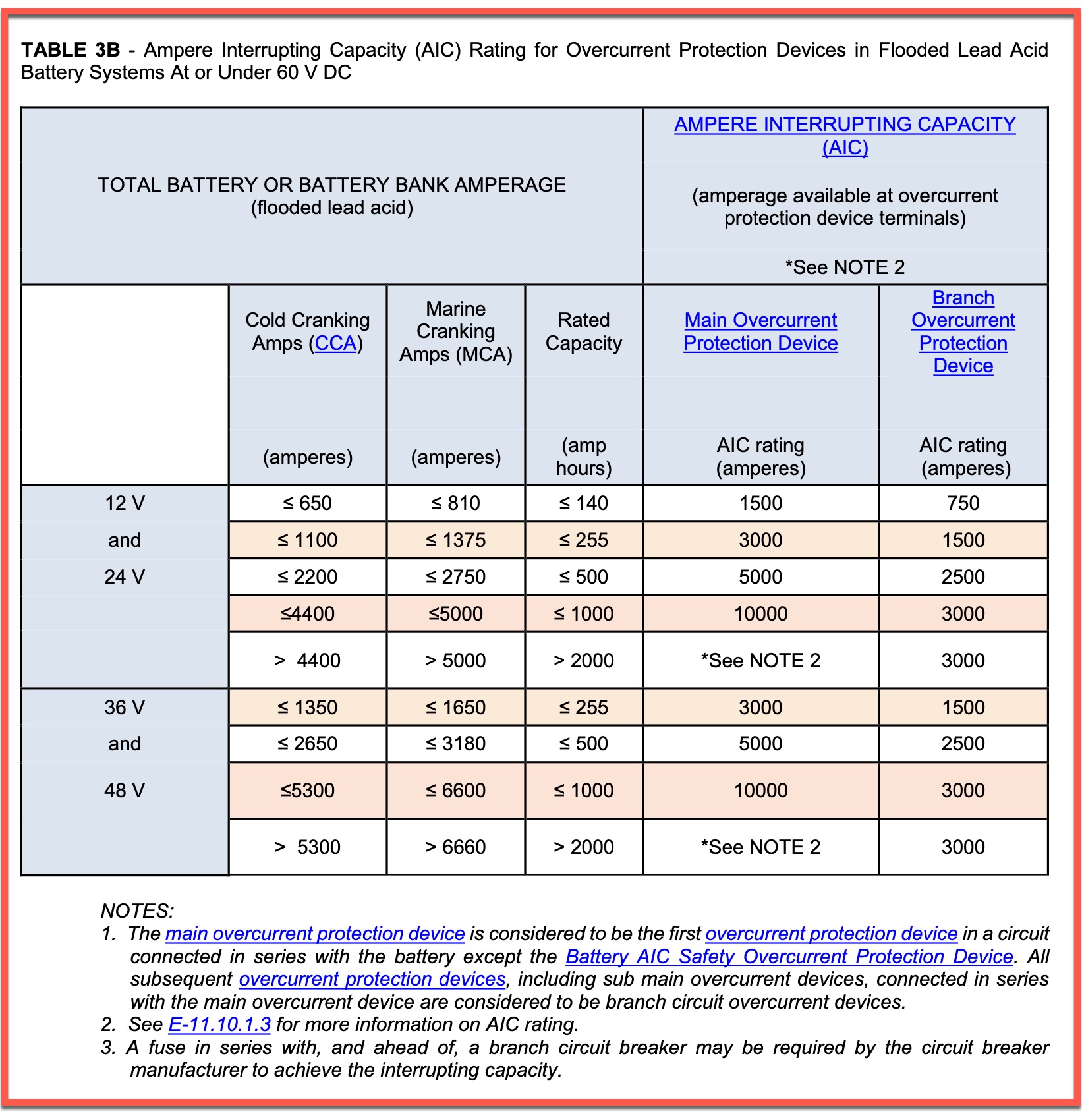
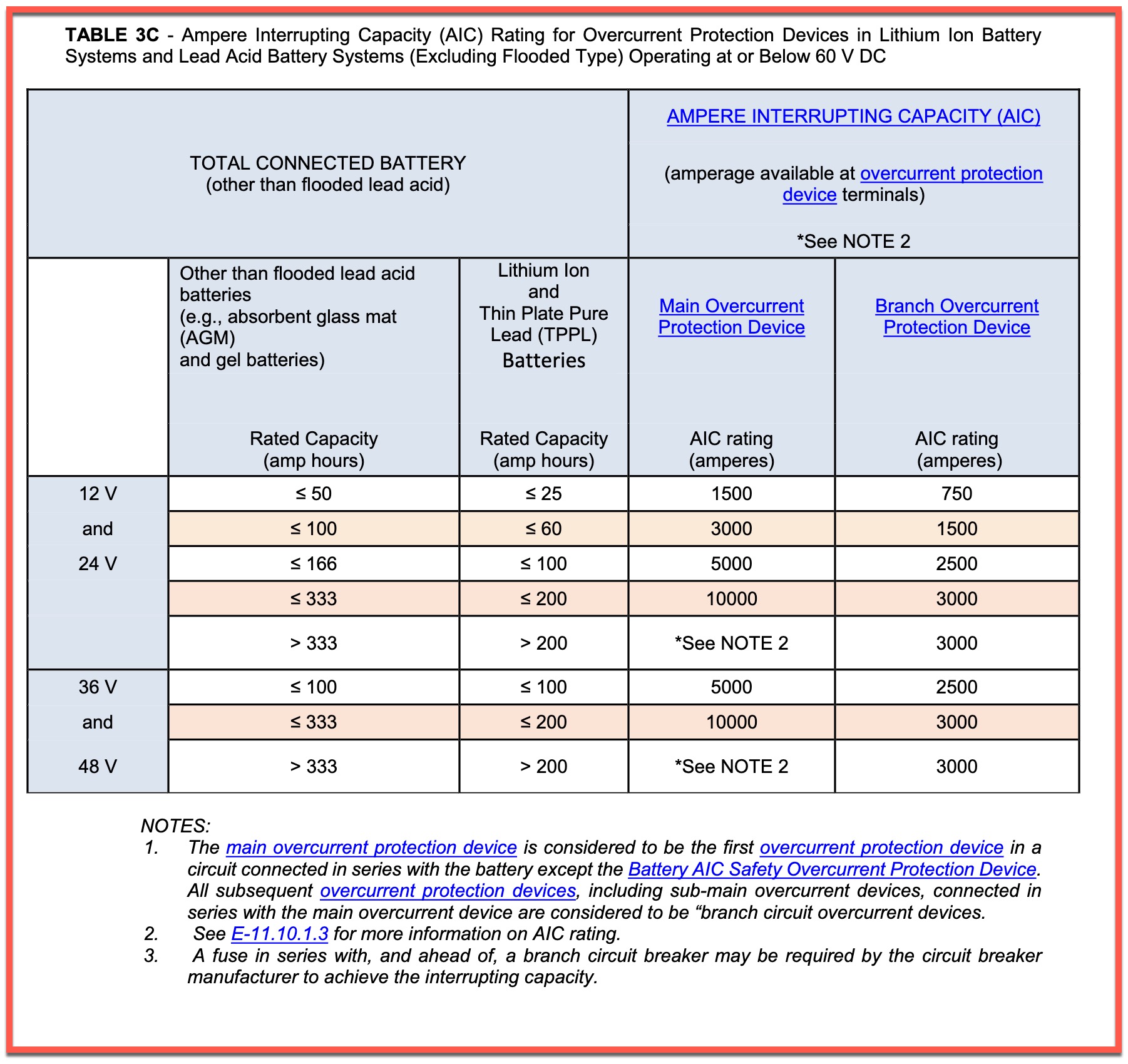
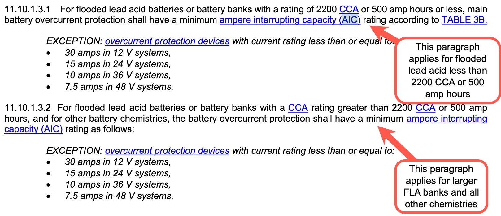
The two tables above show AIC requirements broken down by chemistry. Table 3B defines the AIC required based on CCA, MCA, or rated capacity for flooeded lead acid batteries only. Table 3C defines the same for lead acid batteries other than flooded or TPPL and for TPPL and lithium ion batteries. I think this is a great development for boat builders, installers, and do-it-yourselfers. The update clearly defines the required AIC and scales based on the size of the battery bank. That’s a big improvement over the nearly one sized fits all 20,000 AIC at 125 VDC we had previously for any larger or higher amperage banks.
Solid state overcurrent protection gains approval
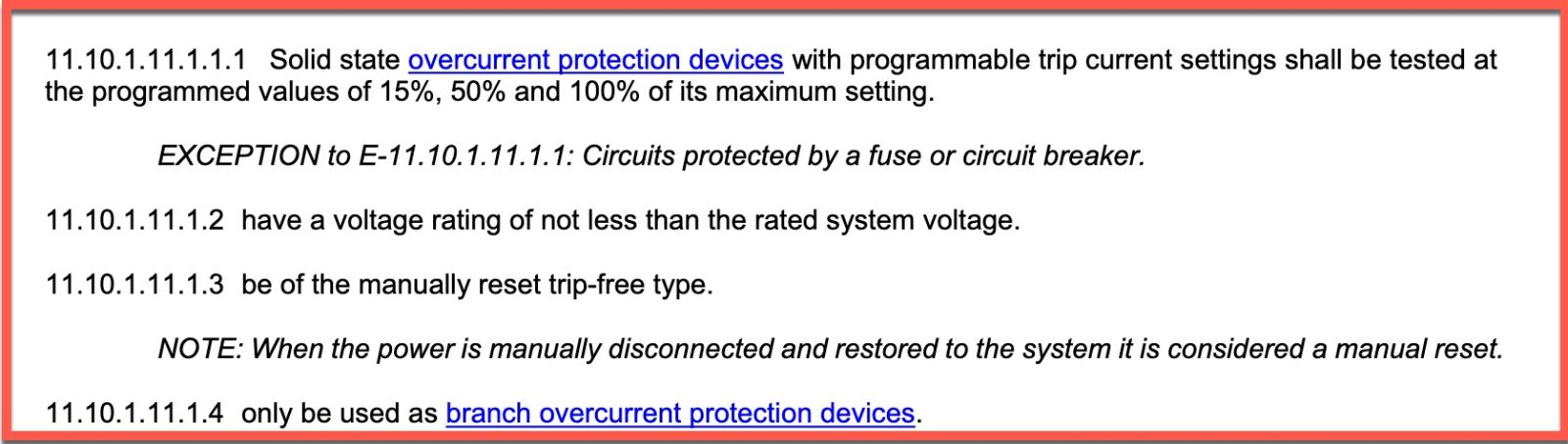
The 2025 revision of E-11 marks the first time the standard allows the use of solid state over current protection devices. This revision only permits their use in branch circuits, not as primary over current protection. Additionally, consistent with E-11’s previous stance, the standard only allows manual resettable breakers.
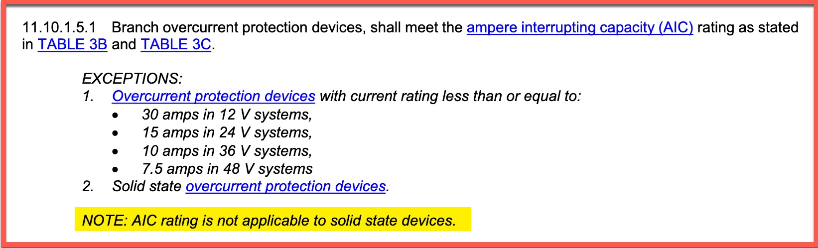
In light of the amount of ink I spilled discussing AIC, it’s worth noting that solid-state devices are not rated for AIC. Hence, there is no AIC requirement for them.
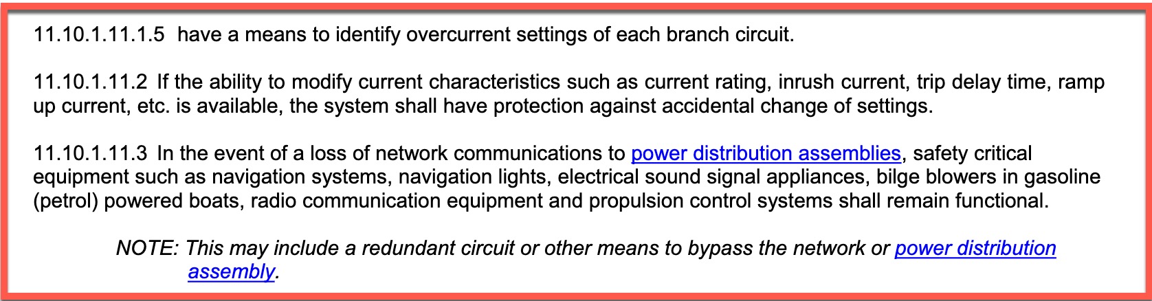
The potential for dynamic reconfiguration of solid-state OCP opens up several new ways to introduce trouble. The standard introduces a requirement the current overcurrent settings are identified and a requirement that those settings not be accidentally changed.
Additionally, 11.10.1.11.3 requires continued operation in the event of a loss of communications between power distribution components. I’m left with a question about the standard’s requirements in the event an OCP device trips due to a valid over current situation. Does 11.10.1.11.3 require there be a method to reset the breaker while communications are down? My gut says it does not, but that’s just my guess.
Individual battery OCP required for larger banks
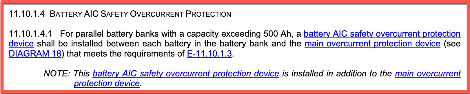
Edit 8/3/2025 – First, a note of thanks to Costin Alexandru, a member of the Facebook group Boat Electrical Systems, for pointing out that I missed covering this change. A new requirement has been added requiring battery banks in excess of 500 amp hours to utilize what the standard calls “battery AIC safety overcurrent protection devices.” I find the description odd and maybe a little confusing. However, my understanding is the intent is that a properly sized fuse must be employed inline before each battery’s output joins the rest of the bank.
E-13 updates
E-13 was first published in July of 2022 and the recently released update is the first revision to the standard. Not surprisingly, there are quite a few changes to the standard. Some of those changes represent significant changes in requirements while others simply work to clarify or streamline requirements.
60 volt updates

Although the change log notes requirements added for batteries operating over 60 volts, the standard contains just a few notes and exceptions for 60 volt or higher systems. In addition to the note above, there is a separate carve out for the 60 volt and greater systems that meet automotive manufacturer requirements or have been approved by classification like ABS, Lloyd’s Register and others.
Definitions update
Overall, the update streamlines the definitions section significantly. Defined terms have been reduced from 24 to 15. This might sound like an odd update but I think it’s a good one. The previous definition section defined terms like high and low temperature cutoffs and events as well as high and low voltage cutoffs and events. Reflective of the approach of the update E-13 overall, there is less specific definition of how the battery is managed. Instead, the standard focuses on safety and simply requires that the battery manage itself to stay in safe ranges.

The July 2022 version of E-13 defined a safe operating envelope in which the battery should operate. The new revison udpates the language to safe operating limits. I don’t love changing terminology though I understand this change was made to harmonize with other standards. Regardless of the terminology, the point is that the BMS’ job is to keep the battery within safe limits. How it does that is more for the battery manufacturer to determine than the standard.
Battery switch clarifications
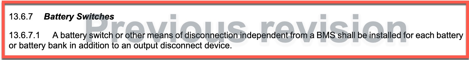
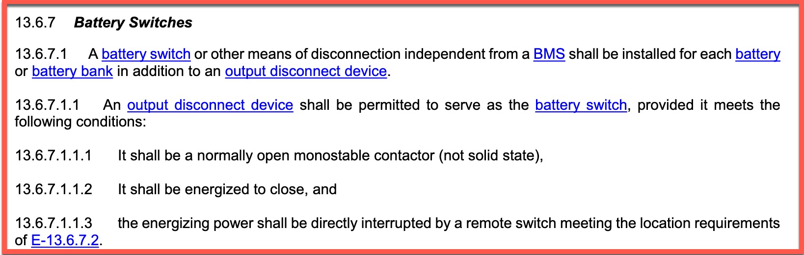
Initially, E-13 required a battery switch. or disconnect “independent from a BMS.” But, this left questions about whether a remotely controlled disconnect controlled by the BMS complied. The new language clarifies the requirements outlining the circumstances under which the BMS output disconnect device can also serve as battery switch. Essentially, a contactor or relay meets the requirements if: 1) it disconnects the circuit when power is removed 2) power is required to close the circuit 3) a manually controlled switch removes power regardless of what the BMS does.
These requirements make clear that, for example, a Mastervolt MLi series battery with some Blue Sea RBS meets the requirements. To be clear, the RBS employed must be what Blue Sea calls auto-releasing, not the bi-stable models. Bi-stable models don’t meet the requirements because they may stay closed if the BMS goes offline and removes power.
Mixed chemistries
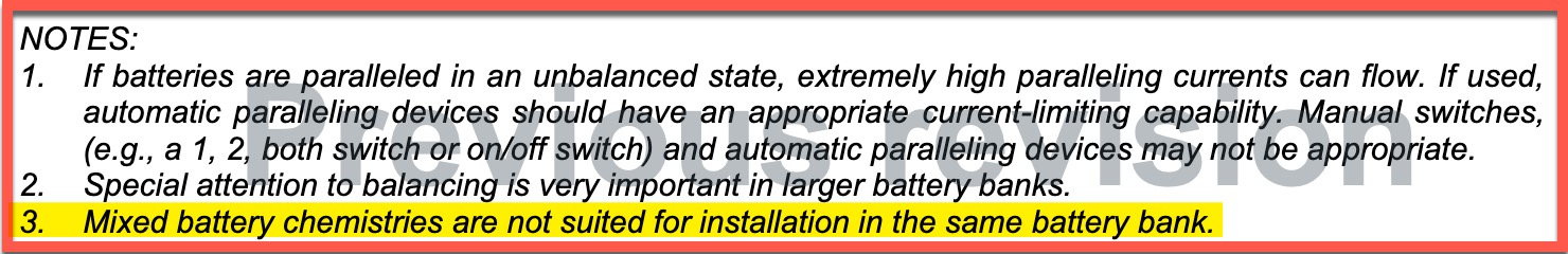
The initial revision of E-13 clearly prohibited mixing of chemistries within a battery bank. Though, that prohibition was in a note on section 13.6.8.2. At the time, that was in line with other safety standards and nearly all battery manufacturer’s guidance. In the last three years, the topic has been revisited with more acceptance. Most mixed chemistry banks combine LiFePO4 and some lead acid. Properly managed, the two chemistries prove complementary in function and behavior.
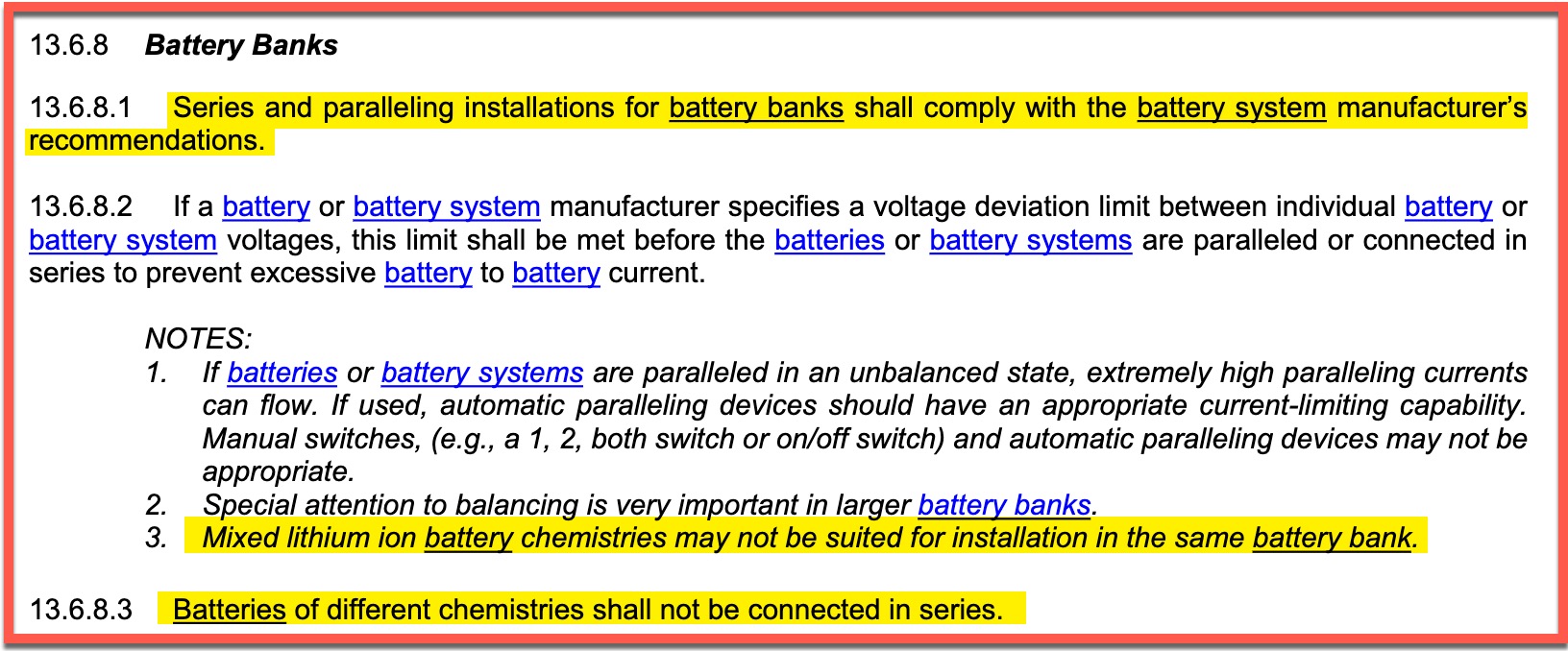
The updated standard takes a more permissive view on mixing chemistries. Although the standard no longer prohibits mixing chemistries, 13.6.8.1 requires battery banks be constructed in compliance with manufacturer recommendations. Many manufacturers still prohibit mixing chemistries with their batteries, so that may limit your ability to create an E-13 compliant, mixed chemistry bank. Note 3 of 13.6.8.2 moves from prohibiting mixed chemistries to noting that mixing lithium ion chemistries might be a bad idea. Additionally (and highly logically) 13.6.8.3 prohibits mixing chemistries within a series bank.
Owner’s manual requirements
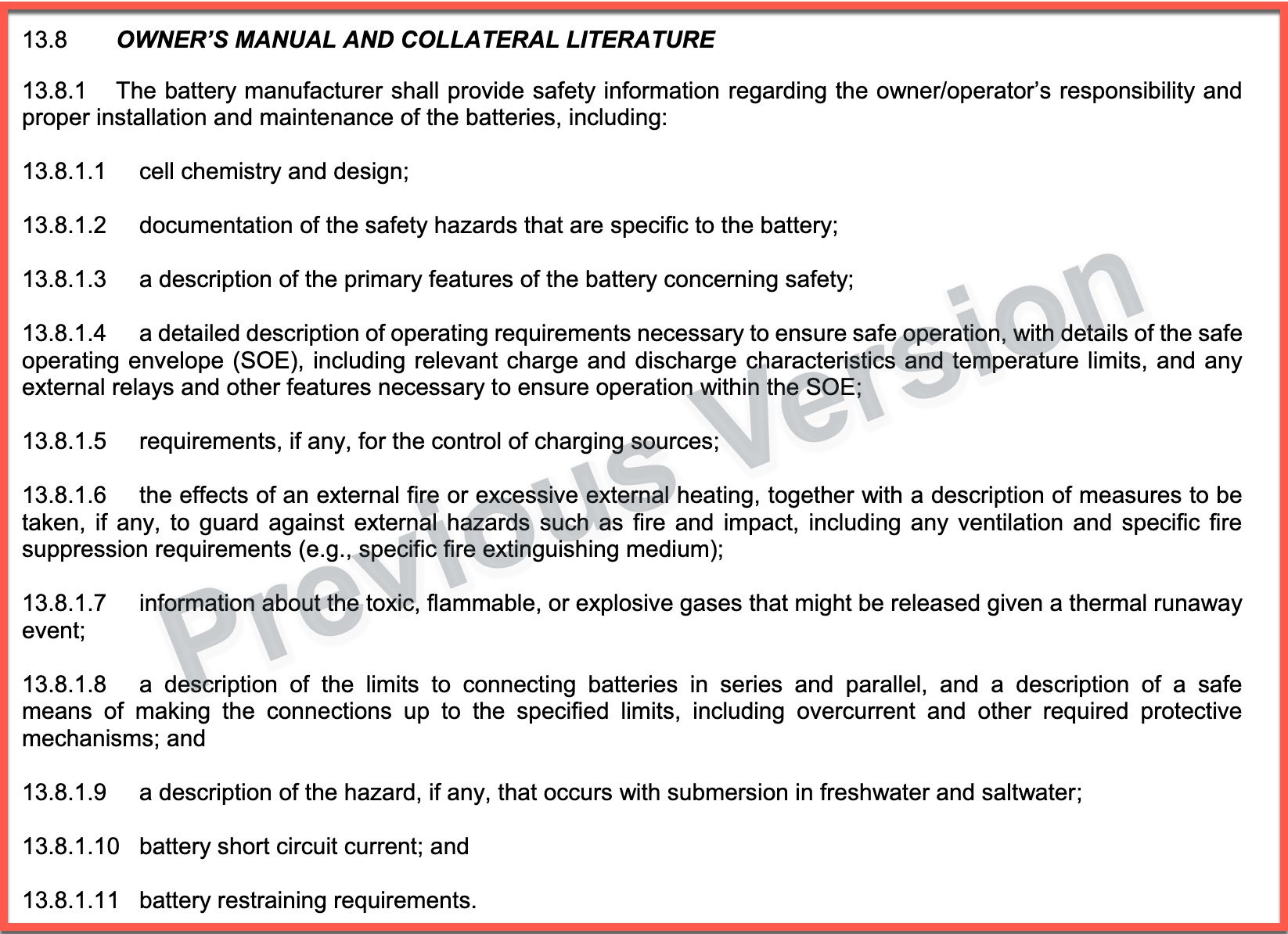
The original publication of E-13 required extensive technical and installation information in the owner’s manual. Looking at each of the requirements, none looked unreasonable. But, it seems battery manufacturers responded with a yawn. I am yet to see a battery manual that clearly meets all the requirements of the July 2022 version of the owners manual requirements. Unfortunately, one of the most often ignored elements is 13.8.1.10, battery short circuit current. Realistically, this is one of the most important specs to properly design a safe electrical system. However, very few manufacturers supply this.
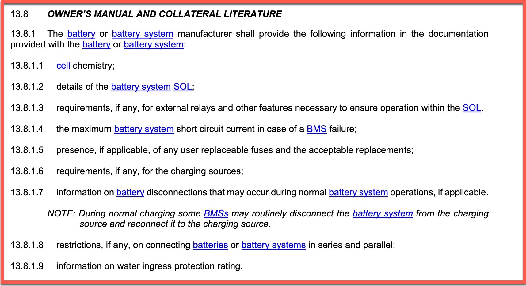
The new section 13.8 greatly streamlines the requirements. I’m hopeful that these much simpler requirements will ease the burden for manufacturers and result in more batteries with compliant information. Overall. the requirements are reduced to just those needed for safe installations. However, short circuit current remains a requirement (as it should) so compliance may still turn on how many manufacturers can supply that information.
Transient voltage appendix
The last major addition to E-13 is an appendix on transient voltage, some causes, and potential for damage. The appendix concentrates on the potential for transients when a charge bus disconnects. It notes that these disconnects may be routine or exceptional depending on battery design.
The appendix provides an excellent overview of transient spikes, their potential causes in lithium ion installations, and means to mitigate them. I think it’s noteworthy that one of the suggested mitigations includes “lead acid batteries integrated into the electrical system to absorb transient voltages.”
Final thoughts
Updates to safety standards may not be the most exciting thing you will encounter in your day. But, lithium batteries and their power density, charge flexibility, and lifespan enable comfort and flexibility on the water that was previously difficult or impossible to achieve. Evolving safety standards help ensure installations are safe, reliable, and insurable. For that reason alone, I think these updates are interesting and dare I say even exciting.


Thanks for the excellent wrap up Ben. Must say I’m surprised how high the AIC ratings required are particularly for Lead Acid batteries. Given the millions of installations in service with significantly lower AIC Over Current Protection in marine, RV and automotive, I’m curious whether (a) this has been a significant issue to date and also (b) if there is readily available information detailing actual battery testing.
I’ve previously spent time searching for short circuit current information specific to LFP batteries with internal BMS’s with mosfet shutoffs. It was extremely hard to find any solid data and it was mostly anecdotal. Getting battery manufacturers to supply this would be a major step forwards.
Batteries (at least the good ones) with a mosfet switch built in will shut off when a short circuit or massive overcurrent is detected, so there basically is no short circuit current to speak off. Unless the mosfets fail, but in that case the manufacturer has to state specifications for a broken product and I don’t see that happening. I think you shouldn’t depend on the mosfets to kill or limit the current in case of a short circuit, and install a fuse according to the battery capacity. (table 3C)
Agreed, this in line with what I have been specifying other than using lower figures than in table 3B and 3C. I should mention I’m primarily dealing with RV applications and am in NZ not USA however I look to USCG and other standards as guidelines for best practice.
As a comparison, if you look at Victron’s Lynx products they show a system example using the Lynx Distributor with paralleled Victron Lithium batteries (no capacity shown) using Mega fuses (generally 2000A AIC). The USCG figures would limit battery size to 40AH max each. I’m sure there are plenty of installations using these with larger batteries, has it really been a problem? And yes, Victron have another Lynx product with 2x Class T’s.
In the RV world there are a heap of 100AH and larger LFP internal BMS/Mosfet batteries installed with no main fuse at all (!), and while I find this very disturbing, anecdotally people seem to be getting away with it.
I was hoping that people may highlight research/testing papers that provide the background for the table 3B/3C USCG figures, and/or case studies where there have been serious incidents caused by inadequate AIC rated OCP.
Much thanks to you Ben for outlining the changes. Super helpful! Ill probably have to read it several times..lol.
Fantastic, thank you! I’ve been hoping someone would write this overview. I know it’s still going to take a while to really wrap my head around these changes, but this is a great overview.
Ben, excellent write up. With the updated clarity it has me reconsidering my OCP on my install from 4 years ago. Current setup is 4 separate strings of 3 24v 50Ahr LFP in parallel each string fused with MBRF fuse at 175 amps to a common bus bar. After the common bus bar I have a 300 amp Class T fuse. Given total bank is 600Ahr does 11.10.1.4 mean I should put a MBRF fuse on each battery at say 50A? Would I also need to split the strings into 1/2 and 3/4 and fuse each with its own 300A class T fuse? Given the clarity of 5000 AIC for each 100Ahr my 600Ahr bank would exceed the class T AIC of 20K amps. So splitting in two would keep each 1/2 and 3/4 strings below 20K amps. Thanks for any inputs.
William,
In order to meet the new requirements, I believe you would need OCP on each battery. 10.11.1.4.1 (excerpted above) states that for banks over 500ah, “a battery AIC safety overcurrent protection device shall be installed between each battery in the battery bank.” I suppose there might be some creative interpretation that says you have four 150 ah battery banks and you’re just joining them, but I don’t think that would strictly meet the new requirements. Note that typically, the requirement in our industry is that an installation comply with the current standards at the time the installation is completed or updated. So, if you don’t make major changes, you are probably technically compliant with the standard when you completed the installation.
-Ben S.
Ben-Excellent summary. Thank you for doing the significant dog work to produce this as you have provided a great resource for anybody that is curious.
Great outline, Ben. Credit to ABYC and all their volunteers.
Good detail, like separating TPPL batteries from other lead acid in the AIC table.
Are we at a point where we should have no fear of boat fires due to Lithium, when these standards are followed?
Are we at a point, any fear of Lithium should instead focus on those cheap consumer devices with in-built lithium batteries, like fans and flashlights, or even not them?
Dan,
Good questions with regards to the state of the technology and the potential concern around its use. First, I don’t think we are at a point where we should lose respect for the energy potential of these batteries. Simply put, they store a lot of energy and they’re willing to dispense that energy quickly weather to a load, a short circuit, or a lose connection generating lots of heat. To that end, systems with this technology must be designed by people who understand the potential and the appropriate mitigations. So, should we fear lithium batteries? I don’t think so, but we certainly should respect them.
I feel much less equipped to answer your second question but will note that the majority of fire casualties I hear about that are attributed to lithium batteries ultimately trace back to batteries brought on the boat in another device. But, those anecdotes might be deceiving as I think there are many more batteries brought on boats in other devices than there are those installed in boats.
-Ben S.
Ben, if to could help me and maybe others on this. On Lithium, a class T fuse on each batter within 7″. Ok! But now from that fuse block/s, that cable goes to a busbar. Is another class T fuse needed between the busbar and the cable suppling the load? Or can another type of fuse be used?
@ Paul
The first fuse off of a battery can be as far away as 72” if the cable is protected. We use FR split loom. Regarding loads off the bus bar: match the OCPD to the conductor ampacity and you will be ABYC E-11 compliant.